
TL;DR:
This blog post explores the color capabilities of AMD hardware and how they are exposed to userspace through driver-specific properties. It discusses the different color blocks in the AMD Display Core Next (DCN) pipeline and their capabilities, such as predefined transfer functions, 1D and 3D lookup tables (LUTs), and color transformation matrices (CTMs). It also highlights the differences in AMD HW blocks for pre and post-blending adjustments, and how these differences are reflected in the available driver-specific properties.
Overall, this blog post provides a comprehensive overview of the color capabilities of AMD hardware and how they can be controlled by userspace applications through driver-specific properties. This information is valuable for anyone who wants to develop applications that can take advantage of the AMD color management pipeline.
Get a closer look at each hardware block’s capabilities, unlock a wealth of knowledge about AMD display hardware, and enhance your understanding of graphics and visual computing. Stay tuned for future developments as we embark on a quest for GPU color capabilities in the ever-evolving realm of rainbow treasures.
Operating Systems can use the power of GPUs to ensure consistent color reproduction across graphics devices. We can use GPU-accelerated color management to manage the diversity of color profiles, do color transformations to convert between High-Dynamic-Range (HDR) and Standard-Dynamic-Range (SDR) content and color enhacements for wide color gamut (WCG). However, to make use of GPU display capabilities, we need an interface between userspace and the kernel display drivers that is currently absent in the Linux/DRM KMS API.
In the previous blog post I presented how we are expanding the Linux/DRM color management API to expose specific properties of AMD hardware. Now, I’ll guide you to the color features for the Linux/AMD display driver. We embark on a journey through DRM/KMS, AMD Display Manager, and AMD Display Core and delve into the color blocks to uncover the secrets of color manipulation within AMD hardware. Here we’ll talk less about the color tools and more about where to find them in the hardware.
We resort to driver-specific properties to reach AMD hardware blocks with color capabilities. These blocks display features like predefined transfer functions, color transformation matrices, and 1-dimensional (1D LUT) and 3-dimensional lookup tables (3D LUT). Here, we will understand how these color features are strategically placed into color blocks both before and after blending in Display Pipe and Plane (DPP) and Multiple Pipe/Plane Combined (MPC) blocks.
That said, welcome back to the second part of our thrilling journey through AMD’s color management realm!
AMD Display Driver in the Linux/DRM Subsystem: The Journey
In my 2022 XDC talk “I’m not an AMD expert, but…”, I briefly explained the organizational structure of the Linux/AMD display driver where the driver code is bifurcated into a Linux-specific section and a shared-code portion. To reveal AMD’s color secrets through the Linux kernel DRM API, our journey led us through these layers of the Linux/AMD display driver’s software stack. It includes traversing the DRM/KMS framework, the AMD Display Manager (DM), and the AMD Display Core (DC) [1].

The DRM/KMS framework provides the atomic API for color management through KMS
properties represented by struct drm_property. We extended the color
management interface exposed to userspace by leveraging existing resources and
connecting them with driver-specific functions for managing modeset properties.
On the AMD DC layer, the interface with hardware color blocks is established. The AMD DC layer contains OS-agnostic components that are shared across different platforms, making it an invaluable resource. This layer already implements hardware programming and resource management, simplifying the external developer’s task. While examining the DC code, we gain insights into the color pipeline and capabilities, even without direct access to specifications. Additionally, AMD developers provide essential support by answering queries and reviewing our work upstream.
The primary challenge involved identifying and understanding relevant AMD DC code to configure each color block in the color pipeline. However, the ultimate goal was to bridge the DC color capabilities with the DRM API. For this, we changed the AMD DM, the OS-dependent layer connecting the DC interface to the DRM/KMS framework. We defined and managed driver-specific color properties, facilitated the transport of user space data to the DC, and translated DRM features and settings to the DC interface. Considerations were also made for differences in the color pipeline based on hardware capabilities.
Exploring Color Capabilities of the AMD display hardware
Now, let’s dive into the exciting realm of AMD color capabilities, where a abundance of techniques and tools await to make your colors look extraordinary across diverse devices.
First, we need to know a little about the color transformation and calibration tools and techniques that you can find in different blocks of the AMD hardware. I borrowed some images from [2] [3] [4] to help you understand the information.
Predefined Transfer Functions (Named Fixed Curves):
Transfer functions serve as the bridge between the digital and visual worlds, defining the mathematical relationship between digital color values and linear scene/display values and ensuring consistent color reproduction across different devices and media. You can learn more about curves in the chapter GPU Gems 3 - The Importance of Being Linear by Larry Gritz and Eugene d’Eon.
ITU-R 2100 introduces three main types of transfer functions:
- OETF: the opto-electronic transfer function, which converts linear scene light into the video signal, typically within a camera.
- EOTF: electro-optical transfer function, which converts the video signal into the linear light output of the display.
- OOTF: opto-optical transfer function, which has the role of applying the “rendering intent”.
AMD’s display driver supports the following pre-defined transfer functions (aka named fixed curves):
- Linear/Unity: linear/identity relationship between pixel value and luminance value;
- Gamma 2.2, Gamma 2.4, Gamma 2.6: pure power functions;
- sRGB: 2.4: The piece-wise transfer function from IEC 61966-2-1:1999;
- BT.709: has a linear segment in the bottom part and then a power function with a 0.45 (~1/2.22) gamma for the rest of the range; standardized by ITU-R BT.709-6;
- PQ (Perceptual Quantizer): used for HDR display, allows luminance range capability of 0 to 10,000 nits; standardized by SMPTE ST 2084.
These capabilities vary depending on the hardware block, with some utilizing hardcoded curves and others relying on AMD’s color module to construct curves from standardized coefficients. It also supports user/custom curves built from a lookup table.
1D LUTs (1-dimensional Lookup Table):
A 1D LUT is a versatile tool, defining a one-dimensional color transformation based on a single parameter. It’s very well explained by Jeremy Selan at GPU Gems 2 - Chapter 24 Using Lookup Tables to Accelerate Color Transformations
It enables adjustments to color, brightness, and contrast, making it ideal for fine-tuning. In the Linux AMD display driver, the atomic API offers a 1D LUT with 4096 entries and 8-bit depth, while legacy gamma uses a size of 256.
3D LUTs (3-dimensional Lookup Table):
These tables work in three dimensions – red, green, and blue. They’re perfect for complex color transformations and adjustments between color channels. It’s also more complex to manage and require more computational resources. Jeremy also explains 3D LUT at GPU Gems 2 - Chapter 24 Using Lookup Tables to Accelerate Color Transformations
CTM (Color Transformation Matrices):
Color transformation matrices facilitate the transition between different color spaces, playing a crucial role in color space conversion.
HDR Multiplier:
HDR multiplier is a factor applied to the color values of an image to increase their overall brightness.
AMD Color Capabilities in the Hardware Pipeline
First, let’s take a closer look at the AMD Display Core Next hardware pipeline in the Linux kernel documentation for AMDGPU driver - Display Core Next
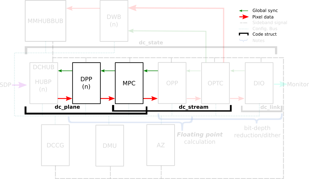
In the AMD Display Core Next hardware pipeline, we encounter two hardware blocks with color capabilities: the Display Pipe and Plane (DPP) and the Multiple Pipe/Plane Combined (MPC). The DPP handles color adjustments per plane before blending, while the MPC engages in post-blending color adjustments. In short, we expect DPP color capabilities to match up with DRM plane properties, and MPC color capabilities to play nice with DRM CRTC properties.
Note: here’s the catch – there are some DRM CRTC color transformations that don’t have a corresponding AMD MPC color block, and vice versa. It’s like a puzzle, and we’re here to solve it!
AMD Color Blocks and Capabilities
We can finally talk about the color capabilities of each AMD color block. As it
varies based on the generation of hardware, let’s take the DCN3+ family as
reference. What’s possible to do before and after blending depends on hardware
capabilities describe in the kernel driver by struct
dpp_color_caps
and struct
mpc_color_caps.
The AMD Steam Deck hardware provides a tangible example of these capabilities.
Therefore, we take SteamDeck/DCN301 driver as an example and look at the “Color
pipeline capabilities” described in the file:
driver/gpu/drm/amd/display/dcn301/dcn301_resources.c
/* Color pipeline capabilities */
dc->caps.color.dpp.dcn_arch = 1; // If it is a Display Core Next (DCN): yes. Zero means DCE.
dc->caps.color.dpp.input_lut_shared = 0;
dc->caps.color.dpp.icsc = 1; // Intput Color Space Conversion (CSC) matrix.
dc->caps.color.dpp.dgam_ram = 0; // The old degamma block for degamma curve (hardcoded and LUT). `Gamma correction` is the new one.
dc->caps.color.dpp.dgam_rom_caps.srgb = 1; // sRGB hardcoded curve support
dc->caps.color.dpp.dgam_rom_caps.bt2020 = 1; // BT2020 hardcoded curve support (seems not actually in use)
dc->caps.color.dpp.dgam_rom_caps.gamma2_2 = 1; // Gamma 2.2 hardcoded curve support
dc->caps.color.dpp.dgam_rom_caps.pq = 1; // PQ hardcoded curve support
dc->caps.color.dpp.dgam_rom_caps.hlg = 1; // HLG hardcoded curve support
dc->caps.color.dpp.post_csc = 1; // CSC matrix
dc->caps.color.dpp.gamma_corr = 1; // New `Gamma Correction` block for degamma user LUT;
dc->caps.color.dpp.dgam_rom_for_yuv = 0;
dc->caps.color.dpp.hw_3d_lut = 1; // 3D LUT support. If so, it's always preceded by a shaper curve.
dc->caps.color.dpp.ogam_ram = 1; // `Blend Gamma` block for custom curve just after blending
// no OGAM ROM on DCN301
dc->caps.color.dpp.ogam_rom_caps.srgb = 0;
dc->caps.color.dpp.ogam_rom_caps.bt2020 = 0;
dc->caps.color.dpp.ogam_rom_caps.gamma2_2 = 0;
dc->caps.color.dpp.ogam_rom_caps.pq = 0;
dc->caps.color.dpp.ogam_rom_caps.hlg = 0;
dc->caps.color.dpp.ocsc = 0;
dc->caps.color.mpc.gamut_remap = 1; // Post-blending CTM (pre-blending CTM is always supported)
dc->caps.color.mpc.num_3dluts = pool->base.res_cap->num_mpc_3dlut; // Post-blending 3D LUT (preceded by shaper curve)
dc->caps.color.mpc.ogam_ram = 1; // Post-blending regamma.
// No pre-defined TF supported for regamma.
dc->caps.color.mpc.ogam_rom_caps.srgb = 0;
dc->caps.color.mpc.ogam_rom_caps.bt2020 = 0;
dc->caps.color.mpc.ogam_rom_caps.gamma2_2 = 0;
dc->caps.color.mpc.ogam_rom_caps.pq = 0;
dc->caps.color.mpc.ogam_rom_caps.hlg = 0;
dc->caps.color.mpc.ocsc = 1; // Output CSC matrix.
I included some inline comments in each element of the color caps to quickly
describe them, but you can find the same information in the Linux kernel
documentation. See more in
struct dpp_color_caps,
struct
mpc_color_caps
and struct rom_curve_caps.
Now, using this guideline, we go through color capabilities of DPP and MPC blocks and talk more about mapping driver-specific properties to corresponding color blocks.
DPP Color Pipeline: Before Blending (Per Plane)
Let’s explore the capabilities of DPP blocks and what you can achieve with a color block. The very first thing to pay attention is the display architecture of the display hardware: previously AMD uses a display architecture called DCE
- Display and Compositing Engine, but newer hardware follows DCN - Display Core Next.
The architectute is described by: dc->caps.color.dpp.dcn_arch
AMD Plane Degamma: TF and 1D LUT
Described by: dc->caps.color.dpp.dgam_ram, dc->caps.color.dpp.dgam_rom_caps,dc->caps.color.dpp.gamma_corr
AMD Plane Degamma data is mapped to the initial stage of the DPP pipeline. It
is utilized to transition from scanout/encoded values to linear values for
arithmetic operations. Plane Degamma supports both pre-defined transfer
functions and 1D LUTs, depending on the hardware generation. DCN2 and older
families handle both types of curve in the Degamma RAM block
(dc->caps.color.dpp.dgam_ram); DCN3+ separate hardcoded curves and 1D LUT
into two block: Degamma ROM (dc->caps.color.dpp.dgam_rom_caps) and Gamma
correction block (dc->caps.color.dpp.gamma_corr), respectively.
Pre-defined transfer functions:
- they are hardcoded curves (read-only memory - ROM);
- supported curves: sRGB EOTF, BT.709 inverse OETF, PQ EOTF and HLG OETF, Gamma 2.2, Gamma 2.4 and Gamma 2.6 EOTF.
The 1D LUT currently accepts 4096 entries of 8-bit. The data is interpreted as an array
of struct drm_color_lut elements. Setting TF = Identity/Default and LUT as
NULL means bypass.
References:
- [PATCH v3 04/32] drm/amd/display: add driver-specific property for plane degamma LUT
- [PATCH v3 05/32] drm/amd/display: add plane degamma TF driver-specific property
- [PATCH v3 19/32] drm/amd/display: add plane degamma TF and LUT support
AMD Plane 3x4 CTM (Color Transformation Matrix)
AMD Plane CTM data goes to the DPP Gamut Remap block, supporting a 3x4 fixed
point (s31.32) matrix for color space conversions. The data is interpreted as a
struct drm_color_ctm_3x4. Setting NULL means bypass.
References:
- [PATCH v3 30/32] drm/amd/display: add plane CTM driver-specific property
- [PATCH v3 31/32] drm/amd/display: add plane CTM support
- [PATCH v3 32/32] drm/amd/display: Add 3x4 CTM support for plane CTM
AMD Plane Shaper: TF + 1D LUT
Described by: dc->caps.color.dpp.hw_3d_lut
The Shaper block fine-tunes color adjustments before applying the 3D LUT,
optimizing the use of the limited entries in each dimension of the 3D LUT. On
AMD hardware, a 3D LUT always means a preceding shaper 1D LUT used for
delinearizing and/or normalizing the color space before applying a 3D LUT, so
this entry on DPP color caps dc->caps.color.dpp.hw_3d_lut means support for
both shaper 1D LUT and 3D LUT.
Pre-defined transfer function enables delinearizing content with or without shaper LUT, where AMD color module calculates the resulted shaper curve. Shaper curves go from linear values to encoded values. If we are already in a non-linear space and/or don’t need to normalize values, we can set a Identity TF for shaper that works similar to bypass and is also the default TF value.
Pre-defined transfer functions:
- there is no DPP Shaper ROM. Curves are calculated by AMD color modules. Check
calculate_curve()function in the fileamd/display/modules/color/color_gamma.c. - supported curves: Identity, sRGB inverse EOTF, BT.709 OETF, PQ inverse EOTF, HLG OETF, and Gamma 2.2, Gamma 2.4, Gamma 2.6 inverse EOTF.
The 1D LUT currently accepts 4096 entries of 8-bit. The data is interpreted as an array
of struct drm_color_lut elements. When setting Plane Shaper TF (!= Identity)
and LUT at the same time, the color module will combine the pre-defined TF and
the custom LUT values into the LUT that’s actually programmed. Setting TF =
Identity/Default and LUT as NULL works as bypass.
References:
- [PATCH v3 10/32] drm/amd/display: add plane shaper LUT and TF
- [PATCH v3 23/32] drm/amd/display: add plane shaper LUT support
- [PATCH v3 24/32] drm/amd/display: add plane shaper TF support
AMD Plane 3D LUT
Described by: dc->caps.color.dpp.hw_3d_lut
The 3D LUT in the DPP block facilitates complex color transformations and
adjustments. 3D LUT is a three-dimensional array where each element is an RGB
triplet. As mentioned before, the dc->caps.color.dpp.hw_3d_lut describe if
DPP 3D LUT is supported.
The AMD driver-specific property advertise the size of a single dimension via
LUT3D_SIZE property. Plane 3D LUT is a blog property where the data is interpreted
as an array of struct drm_color_lut elements and the number of entries is
LUT3D_SIZE cubic. The array contains samples from the approximated function.
Values between samples are estimated by tetrahedral interpolation
The array is accessed with three indices, one for each input dimension (color
channel), blue being the outermost dimension, red the innermost. This
distribution is better visualized when examining the code in
[RFC PATCH 5/5] drm/amd/display: Fill 3D LUT from userspace by Alex Hung:
+	for (nib = 0; nib < 17; nib++) {
+		for (nig = 0; nig < 17; nig++) {
+			for (nir = 0; nir < 17; nir++) {
+				ind_lut = 3 * (nib + 17*nig + 289*nir);
+
+				rgb_area[ind].red = rgb_lib[ind_lut + 0];
+				rgb_area[ind].green = rgb_lib[ind_lut + 1];
+				rgb_area[ind].blue = rgb_lib[ind_lut + 2];
+				ind++;
+			}
+		}
+	}
In our driver-specific approach we opted to advertise it’s behavior to the userspace instead of implicitly dealing with it in the kernel driver. AMD’s hardware supports 3D LUTs with 17-size or 9-size (4913 and 729 entries respectively), and you can choose between 10-bit or 12-bit. In the current driver-specific work we focus on enabling only 17-size 12-bit 3D LUT, as in [PATCH v3 25/32] drm/amd/display: add plane 3D LUT support:
+		/* Stride and bit depth are not programmable by API yet.
+		 * Therefore, only supports 17x17x17 3D LUT (12-bit).
+		 */
+		lut->lut_3d.use_tetrahedral_9 = false;
+		lut->lut_3d.use_12bits = true;
+		lut->state.bits.initialized = 1;
+		__drm_3dlut_to_dc_3dlut(drm_lut, drm_lut3d_size, &lut->lut_3d,
+					lut->lut_3d.use_tetrahedral_9,
+					MAX_COLOR_3DLUT_BITDEPTH);
A refined control of 3D LUT parameters should go through a follow-up version or generic API.
Setting 3D LUT to NULL means bypass.
References:
- [PATCH v3 09/32] drm/amd/display: add plane 3D LUT driver-specific properties
- [PATCH v3 25/32] drm/amd/display: add plane 3D LUT support
AMD Plane Blend/Out Gamma: TF + 1D LUT
Described by: dc->caps.color.dpp.ogam_ram
The Blend/Out Gamma block applies the final touch-up before blending, allowing users to linearize content after 3D LUT and just before the blending. It supports both 1D LUT and pre-defined TF. We can see Shaper and Blend LUTs as 1D LUTs that are sandwich the 3D LUT. So, if we don’t need 3D LUT transformations, we may want to only use Degamma block to linearize and skip Shaper, 3D LUT and Blend.
Pre-defined transfer function:
- there is no DPP Blend ROM. Curves are calculated by AMD color modules;
- supported curves: Identity, sRGB EOTF, BT.709 inverse OETF, PQ EOTF, HLG inverse OETF, and Gamma 2.2, Gamma 2.4, Gamma 2.6 EOTF.
The 1D LUT currently accepts 4096 entries of 8-bit. The data is interpreted as an array
of struct drm_color_lut elements. If plane_blend_tf_property != Identity TF,
AMD color module will combine the user LUT values with pre-defined TF into the
LUT parameters to be programmed. Setting TF = Identity/Default and LUT to NULL
means bypass.
References:
- [PATCH v3 11/32] drm/amd/display: add plane blend
- [PATCH v3 27/32] drm/amd/display: add plane blend LUT and TF support
MPC Color Pipeline: After Blending (Per CRTC)
DRM CRTC Degamma 1D LUT
The degamma lookup table (LUT) for converting framebuffer pixel data before
apply the color conversion matrix. The data is interpreted as an array of
struct drm_color_lut elements. Setting NULL means bypass.
Not really supported. The driver is currently reusing the DPP degamma LUT block
(dc->caps.color.dpp.dgam_ram and dc->caps.color.dpp.gamma_corr) for
supporting DRM CRTC Degamma LUT, as explaning by [PATCH v3 20/32]
drm/amd/display: reject atomic commit if setting both plane and CRTC
degamma.
DRM CRTC 3x3 CTM
Described by: dc->caps.color.mpc.gamut_remap
It sets the current transformation matrix (CTM) apply to pixel data after the
lookup through the degamma LUT and before the lookup through the gamma LUT. The
data is interpreted as a struct drm_color_ctm. Setting NULL means bypass.
DRM CRTC Gamma 1D LUT + AMD CRTC Gamma TF
Described by: dc->caps.color.mpc.ogam_ram
After all that, you might still want to convert the content to wire encoding.
No worries, in addition to DRM CRTC 1D LUT, we’ve got a AMD CRTC gamma transfer
function (TF) to make it happen. Possible TF values are defined by enum
amdgpu_transfer_function.
Pre-defined transfer functions:
- there is no MPC Gamma ROM. Curves are calculated by AMD color modules.
- supported curves: Identity, sRGB inverse EOTF, BT.709 OETF, PQ inverse EOTF, HLG OETF, and Gamma 2.2, Gamma 2.4, Gamma 2.6 inverse EOTF.
The 1D LUT currently accepts 4096 entries of 8-bit. The data is interpreted as an array
of struct drm_color_lut elements. When setting CRTC Gamma TF (!= Identity)
and LUT at the same time, the color module will combine the pre-defined TF and
the custom LUT values into the LUT that’s actually programmed. Setting TF =
Identity/Default and LUT to NULL means bypass.
References:
- [PATCH v3 12/32] drm/amd/display: add CRTC gamma TF driver-specific property
- [PATCH v3 15/32] drm/amd/display: add CRTC gamma TF support
Others
AMD CRTC Shaper and 3D LUT
We have previously worked on exposing CRTC shaper and CRTC 3D LUT, but they were removed from the AMD driver-specific color series because they lack userspace case. CRTC shaper and 3D LUT works similar to plane shaper and 3D LUT but after blending (MPC block). The difference here is that setting (not bypass) Shaper and Gamma blocks together are not expected, since both blocks are used to delinearize the input space. In summary, we either set Shaper + 3D LUT or Gamma.
Input and Output Color Space Conversion
There are two other color capabilities of AMD display hardware that were
integrated to DRM by previous works and worth a brief explanation here. The DC
Input CSC sets pre-defined coefficients from the values of DRM plane
color_range and color_encoding properties. It is used for color space
conversion of the input content. On the other hand, we have de DC Output CSC
(OCSC) sets pre-defined coefficients from DRM connector colorspace
properties. It is uses for color space conversion of the composed image to the
one supported by the sink.
References:
- [PATCH] amd/display/dc: Fix COLOR_ENCODING and COLOR_RANGE doing nothing for DCN20+
- [PATCH v6 00/13] Enable Colorspace connector property in amdgpu
The search for rainbow treasures is not over yet
If you want to understand a little more about this work, be sure to watch Joshua and I presented two talks at XDC 2023 about AMD/Steam Deck colors on Gamescope:
- The rainbow treasure map: advanced color management on Linux with AMD/Steam Deck
- Rainbow Frogs: HDR + Color Management in Gamescope/SteamOS
In the time between the first and second part of this blog post, Uma Shashank and Chaitanya Kumar Borah published the plane color pipeline for Intel and Harry Wentland implemented a generic API for DRM based on VKMS support. We discussed these two proposals and the next steps for Color on Linux during the Color Management workshop at XDC 2023 and I briefly shared workshop results in the 2023 XDC lightning talk session.
The search for rainbow treasures is not over yet! We plan to meet again next year in the 2024 Display Hackfest in Coruña-Spain (Igalia’s HQ) to keep up the pace and continue advancing today’s display needs on Linux.
Finally, a HUGE thank you to everyone who worked with me on exploring AMD’s color capabilities and making them available in userspace.